

S2K Commerce - Products Dropdown
Actions
Web Content Viewer
Actions
Learning Center
Charge Air Coolers Explained
September 9, 2020
The air induction system of modern diesel engines is fundamental in providing the engine with the proper amount of air to ensure longevity and maximize power. This system has many parts. The turbocharger gets most of the attention. But, what about the charge air cooler?
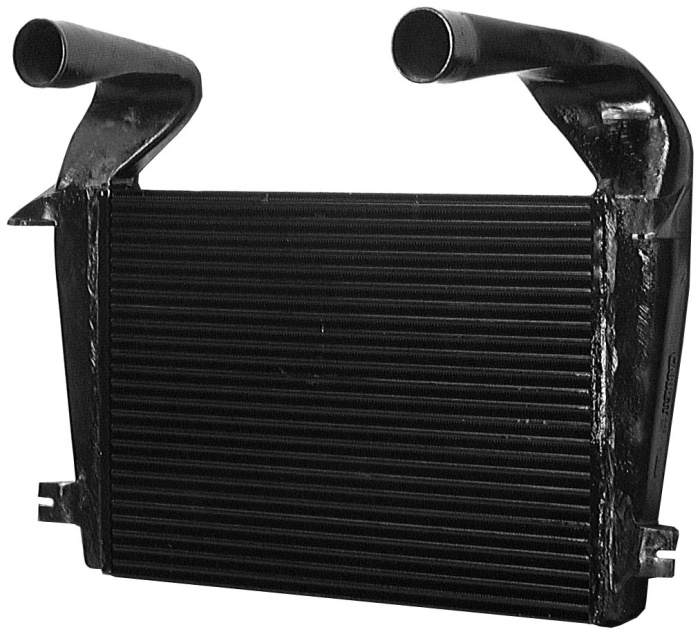
Charge air coolers (CAC) are very important components of diesel engines. Despite its importance, this integral part is ignored during regular fleet maintenance and leaks can go unnoticed and unaddressed. Over time, CACs gradually develop leaks, primarily due to thermal fatigue. When these leaks are minor, fuel mileage may appear to be OK. Fuel economy might be down a little bit, but it often gets written off; it is probably just that lead-footed driver, poor driving habits or an aging engine. However, a lack of power eventually becomes quite noticeable – one may even start to hear whistling. Once that happens, the charge air cooler is officially bad!
What is a charge air cooler?
Charge air coolers work in tandem with turbochargers. A turbocharger compresses air flowing into a vehicle before it enters the intake manifold of an engine. The “charged air” that exits a turbocharger is very hot. To increase combustion efficiency, a charge air cooler does exactly what its name implies: it cools the charged air exiting a turbocharger before it enters an engine (Figure 1).

Figure 1
How does a charge air cooler do its job?
The most common way compressed air is cooled by charge air coolers is through a tube and fin design (Figure 2, Figure 3). In a CAC with a tube and fin design, compressed air from the turbocharger enters the charge air cooler and travels through tubes, which are connected to fins.

Figure 2
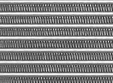
Figure 3
Through the principle of diffusion, heat is transferred from the compressed air to the fins. The charge air cooler fins are continually cooled by ambient air drawn across them by the engine cooling fan or air being forced into the engine compartment by road speeds. Another design of CACs that is becoming more and more popular is referred to as “bar and plate” (Figure 4). In this design, bars and plates are stacked to contain the internal fins, rather than using an extruded aluminum tube – imagine building a box using 2x10s and plywood; this creates a more robust CAC, but it also makes the unit heavier and more expensive, due to the use of additional materials. In some designs of CACs, engine coolant is utilized in conjunction with ambient air to dissipate heat.
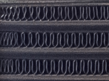
Figure 4
Why compress and cool air?
The answer is simple: air density. The cooled, compressed air is denser than the hot air that originally entered the CAC. As a result, when compressed air flows into the intake manifold and to the cylinder of the engine, the increased density improves fuel economy, horsepower and reduces emissions. Essentially, by cooling compressed air, more of it can be “stuffed” into fixed spaces (cylinders); the dense air contains a greater amount of oxygen than ambient air, which allows the engine to more efficiently burn fuel and create a large energy (or power) yield.
Why do leaking charge air coolers matter?
When you have a leaking charge air cooler, it is estimated that you can lose up to 0.5 MPG in fuel economy. For fleets or owner-operators who average a lot of windshield time throughout the year, the cost of a leaky CAC could be thousands of dollars in wasted fuel. In addition to the monetary cost, poor engine performance and component failures often result from unaddressed leaks. Some of the most common problems that occur as a result of a leaking CAC include:
- Turbocharger failure – An imbalance of pressure due to a leaking CAC could push oil out of the intake (compressor) side of the turbocharger causing black smoke, and can even lead to the turbine wheel contacting the turbo housing
- Loss of power – Utilizing air which is hotter and less dense during the combustion cycle will decrease volumetric efficiency of an engine
- Increased fuel consumption – As a result of power loss, more fuel is consumed to maintain the vehicle performance demands (e.g. more fuel is needed to go 55 MPH)
- Premature piston, ring and valve failure – Hotter air temperatures entering the cylinder as well as incomplete combustion lead to degradation of internal engine components
- Elevated coolant temperatures – Cooling jackets within an engine will be exposed to excess heat, raising the temperature of coolant that is flowing through them
- Exhaust manifold failure – Temperatures of exhaust exiting through the manifold could be elevated due to inefficient combustion
- Increased emission levels – Unburnt fuel (caused by a lack of oxygen during the combustion cycle) will lead to the creation of soot (particulate matter) and higher cylinder temperatures will lead to the forming of NOx and other greenhouse gases
When is the right time to replace a charge air cooler?
Charge air coolers may often be a forgotten part of the diesel engine, but by proactively pressure testing them, leaks can be detected before money is wasted on lost fuel economy, poor performance or component failure. Leaking CACs should not be ignored; they should be repaired or replaced. In addition if upstream components fail (e.g. a turbocharger impeller breaks apart sending shrapnel downstream) or unfortunate circumstances occur (e.g. a vehicle is in an accident twisting and torqueing the CAC), the charge air cooler should be replaced, not left to degrade over time.
More questions about charge air coolers?
Click here to scroll to the top of the page
IMS Relays
April 7, 2020
When walking through a service bay, I, inevitably, see brand new pieces of hardware, taken off a starter motor, scattered through the scrap pile or pail. These small, seemingly insignificant relays are commonly called the IMS (Integrated Magnetic Switch) or Starter Relay (figure 1); they are a starter’s best friend, and should be used, not thrown in the scrap heap. An IMS solves many common starting issues related to voltage drop.
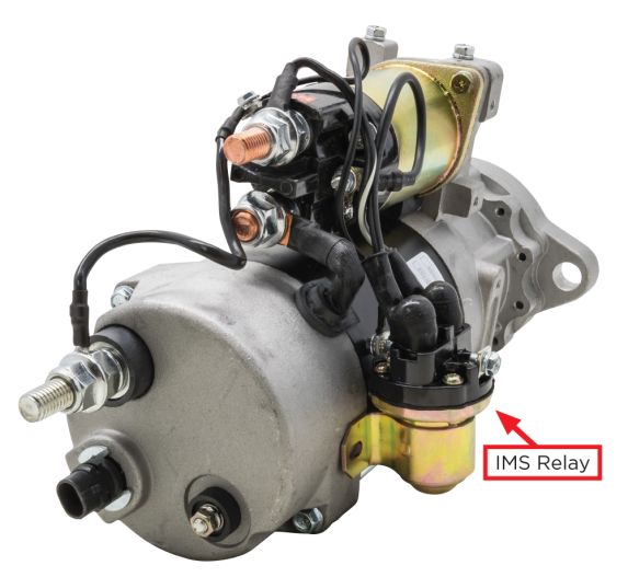
Figure 1
Starting basics
We take the act of starting a vehicle for granted. In reality, it is a pretty incredible process: A 30-pound electrical motor single-handedly starts a 2-ton engine in seconds. Distilling the starter down into basic components (ignoring wiring or batteries), we can look at how the starter operates. Once the key-switch is turned, power flows into the “S” terminal on main motor solenoid. This energizes the solenoid coil, creating a magnetic field. This field pulls on the solenoid plunger – the plunger has a copper contact on one end and a lever connected to the drive/Bendix on the other end. The lever end of the plunger has a heavy-duty spring that helps hold the drive away from the engine’s ring gear when not cranking. This spring requires a lot of power to be compressed, typically 25-35 pounds of force. On the other end, when the coil is energized, the plunger and contact move forward and connect with two other heavy-duty contacts inside the solenoid, creating an electrical “bridge”. These two contacts are the Battery+ and the Motor terminal. With this temporary bridge in place, power can flow across the solenoid and into the starter motor, powering the field coils, armature and brushes. The motor will start to turn, “cranking” the engine.
How does a starter get power?
The main starter solenoid coils draw power from the “S” or switch terminal. This is the terminal which is connected to the ignition circuit of the vehicle’s key-switch or push-button start. The wiring in an ignition circuit is typically between 12 and 16 gauge, and on some vehicles, it can be upwards of 10 feet long. The main starter solenoid coils may need as much as 150 amps in order to close the primary contacts and compress the heavy-duty spring mentioned above; this is referred to as the “pull-in” current.
This “pull-in” process must accomplish several key things: it pushes the starter drive forward engaging the ring gear and closes the primary contacts inside the solenoid as fast as possible, this helps prolong contact life. Once the contacts are closed, the motor solenoid switches over to “hold-in” mode; at this point it is only drawing around 50 amps. This whole process only takes a split second; however, if at any point the voltage drops too low in the hold-in coil will not have enough power to keep the spring compressed, and the contacts will break apart; and the starter will stop cranking.
What is voltage drop?
Voltage drop is caused by electrical resistance and measured in ohms. Manufacturers recommend no more than 0.5 volts drop in any given circuit. Causes of voltage drop can be attributed to a variety of inherent factors such as cable gauge size and length of cable, but voltage drop can also be caused by environmental factors such as corrosion, broken strands or work hardening.
The Simple Starting System
In an older style starting system, a heavy gauge wire would run directly from the battery to the ignition switch then to the starter solenoid. While heavy gauge wires are less susceptible to voltage drop, this style of powering the starter solenoid was inefficient: it used heavy gauge wire which is more expensive due to the high copper content and it created multiple opportunities for voltage drop, as the cable from the battery was not routed directly to the starter. To solve these issues, vehicle manufacturers introduced electrical relays.
Electrical Relays
Electrical relays or relay switches have been around for ages. They come in all shapes and sizes, are referred to by different names and serve various purposes. The ultimate goal is to “make” and “break” (couple and decouple) an electrical circuit, just like a light-switch. It is a whole lot easier (and safer) to switch a light on or off with a simple flick, than to take two wires and twist them together to turn on a light.
Relays use a small electrical signal from the key-switch or push button to ‘flick’ the switch. In their simplest form, a relay contains a set of stationary contacts, a moveable contact, a switch terminal, and a coil. The coil is powered by that small electrical signal, when energized it creates a magnetic field that moves the movable contact (Figure 2). Once contact is made between the larger stationary and moveable contacts; power can flow through the relay. Relays reduce the distances heavy gauge wires need to be routed! Relays are used to control the flow of the electricity from afar, and all you need is a small signal wire.

Figure 2
Firewall Relays
Using a relay to aid in the starting process is not new. Firewall relays (figure 3) were and are quite popular; they are commonly called Ford relays, due to their popular usage with gasoline engines with ignition coils. True to their namesake, firewall relays are normally mounted on the engine firewall. As technologies change and advance, these relays have steadily migrated closer and closer to the starter, reducing the distance needed for the relay to “signal” the solenoid. The most current versions come pre-wired and attached to the starter, or as in the case of Delco’s 2nd Generation 35MT, the relay is built into the motor solenoid; this style of relay is called an Integrated Magnetic Switch or IMS (figure 4).

Figure 3

Figure 4
Integrated Magnetic Switch (IMS)
An IMS acts as a relay between the Battery Positive Stud on the main solenoid and the “S” or switch terminal on the main solenoid. When energized it bridges the two terminals and allows power to flow from the heavy gauge battery positive cable over to the switch terminal, engaging the starter. This relay action helps reduce the power losses or voltage drop experienced by the engagement of the main starter solenoid.
With proper wiring and using the IMS, you can ensure that the electrical current is being routed through the proper sized cabling. Simply put: the standard ignition wiring circuit is not designed to carry the electrical loads that the main starter solenoid draws. By using an IMS, which has much smaller coils and therefore requires less power to engage (typically, around 2 or 3 amps), less power is wasted, and you can have more reliable starting.
Vehicles with IMS relays are less likely to see the myriad of problems seen in field today:
- Non-warrantable damage on the motor solenoids caused by low voltage - soot builds up inside the solenoid, impeding good electrical connection
- Poor reliability in cold weather starting - slow cranking, failed starting attempts
- “Click-no-crank” starting attempts - commonly solved with a screwdriver
- Rapid re-engagement (AKA ‘machine-gun’ starting) - very damaging to the vehicle’s ring gear
IMS relays can be easily retrofitted or added to any application. They can be used in tandem with Fire-wall relays and computer controlled starting processes.
Call us today if you have any questions about how to wire in an IMS on your starter.
Click here to scroll to the top of the page
Diagnostic Tips for Diesel Particulate Filter (DPF) Bypass Failure
July 11, 2019
“There are many forms of DPF failure; the most common failure mode is called 'bypass'.”

Exhaust aftertreatment is one of the top maintenance costs. The biggest reason for this is misdiagnosis, which leads to repairs that fix the symptom, but not the root cause. Diesel particulate filters (DPFs) are maintenance items, meaning they are designed to be cleaned and reused multiple times. If maintained properly, they should not have to be replaced on a regular basis. DPFs are not mechanical – there are no moving parts. When a DPF does fail, it is indicative of a problem somewhere else on the vehicle. Before you change another DPF, read on to find out where your problem really is.
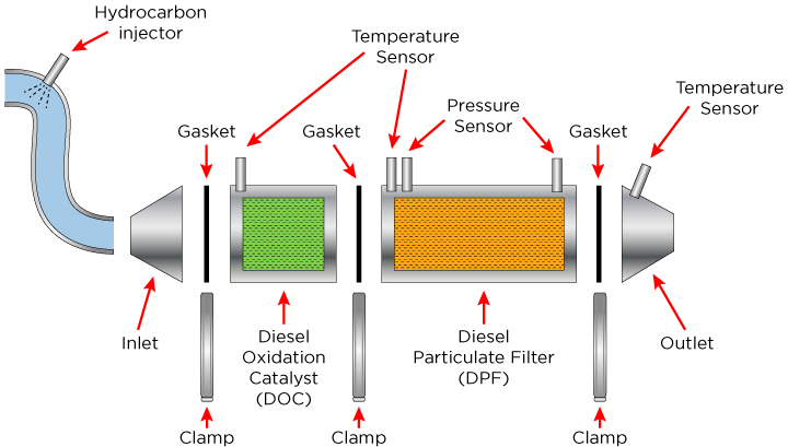
Figure 1
Around 2007, all over-the-road diesel powered commercial vehicles were outfitted with a particulate matter trap in the exhaust system. Typical particulate filtration configurations (Figure 1) consist of a hydrocarbon injector or fuel source, a diesel oxidation catalyst (DOC), a diesel particulate filter (DPF) and temperature and delta pressure sensors. They are held together with gaskets and V-band clamps. The DPF is the particulate matter trap, blocking 95-99.9% of elemental carbon (soot or ash) from moving downstream; it is commonly constructed of a wall-flow monolith, which is easily distinguished by the checkboard pattern at the inlet and outlet (Figure 2). The DOC oxidizes soot during passive regeneration and acts as the primary heat source during active regeneration (regeneration will be discussed in a future article).
What is bypass?
There are many forms of DPF failure; the most common failure mode is called “bypass.” DPF bypass occurs when particulate matter escapes the DPF and exits the vehicle’s exhaust unfiltered (Figure 3). Typically, bypass occurs when there is a breech in cell walls due to an uncontrolled thermal event (Figure 4). The uncontrolled thermal events take place when excessive soot or raw fuel are present in a DPF during active regeneration. According to a publication by the SAE International, most DPF issues are caused by “(1) poor, slow regeneration, or (2) rapid, ‘uncontrolled’ regeneration.”*

Figure 2

Figure 3
As mentioned previously, DPFs are not mechanical – they are the waste basket of the exhaust system. When a DPF is in bypass, it’s similar to a trash bin with a hole in the bottom – it’s no longer doing its job. The question to ask is, “How did that hole get there?” If the waste basket is swapped for a new one and the garbage that caused the hole in the first place continues to get thrown into it, then the symptom was fixed – not the problem that caused it. This is often the case when mechanics change out bypassing DPFs.
Why do you need to diagnose the upstream failure?
In nearly every instance, bypass failures are due to unresolved upstream faults, such as over-fueling or exhaust leaks. If a mechanic decides to simply replace a DPF that is in bypass and not resolve the upstream failure, they will continue replacing costly DPFs over and over again. Often when this type of misdiagnosis occurs, the new replacement DPF may fail within a matter of a few weeks or even days!
Before removing your DPF, it is essential to determine what caused the DPF to fail in the first place. The number one question that needs an answer is: What is the root cause of the DPF failure? Determining the root cause of a DPF failure requires a true diagnostic technician. Diagnostic technicians find the root cause of a failure first, before replacing any component. This is vastly different than swapping expensive aftertreatment parts and hoping that the problem is solved.

Figure 4
How do you properly diagnose a DPF failure?
When you have a DPF failure or receive an engine fault code for your exhaust aftertreatment system, check out the following items before simply replacing your DPF:
- Prioritize and correct current diagnostic trouble-shooting codes (DTCs) or any DTCs saved in history before replacing the DPF.
- Install any new calibration updates. Many DPF and exhaust aftertreatment issues can be solved with a simple calibration update.
- Check your EGR and turbocharging systems are working properly. For example, test EGR valve position and turbocharger vane response.
- Ensure your fuel injection system is operating correctly. For example, test your fuel injection balance rates.
- Check your hydrocarbon injector for carbon build up, volume of fuel being injected and metering valve performance.
- Look for leaks. Exhaust leaks are detrimental to your exhaust aftertreatment system and, if unresolved, can lead to premature DPF failures. Although some exhaust leaks are easy to find, many smaller leaks require a high-pressure smoke machine to identify.
- Inspect the condition of your DPF. Signs of coolant, oil or raw fuel ingestion can be indications of why the unit failed in the first place. Be sure to look at the outlet side of the DPF to determine if there has been significant bypass.
- Any time you remove a DPF, also inspect the DOC, exhaust gas temperature sensors and the differential pressure sensor and tubing. These components are critical to ensuring that your DPF is working properly.
Remember, finding the root cause of your DPF failure before you remove it is key to saving money on costly replacement components.
Still have questions about your exhaust aftertreatment system?
Click here to scroll to the top of the page